Elements of the 24xLink Design....
First some background information.....it is worth the read.
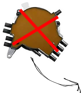
LTx engines came from the factory with the opti-spark distributor. Contained inside the Opti-spark is an optical sensor and a timing disc which has two rows of notches. The first row contains 360 evenly spaced notches, the second row has 8 notches of different sizes to indicate certain cylinder position. This optical sensor and disc are what makes up the "opti" in "opti-spark". The second system at work in the optispark, the "spark" portion, is a more traditional rotor and cap distributor which distributes high tension spark to the engines spark plugs. The LTx engine's PCM used the information from the opti-sparks optical sensor and timing disc to know where all the cylinders are in terms of precise engine angular rotation. Knowing the exact engine position the LT Gen 2 PCM would then calculate and electronically tell the optispark when to fire the high tension leads. Quite a good system, but there is always room for improvement.....
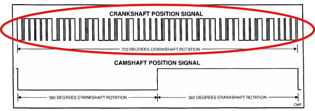
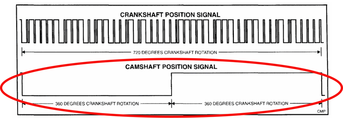
After the LT engines came GM's Gen 3 LS series of engines, particularly at this point in time the "LS1". On LS series engines GM decided to do away with a rotor and cap distributor (and the problems that accompanied the opti-spark) and use a coil-per-cylinder ignition system. Also where the opti-spark had its optical sensor and timing disc, the LS series engine came with its own new system of detecting accurate angular engine position. This new position system used a crankshaft reluctor and camshaft reluctor. The crankshaft reluctor has 24 unique pulses per 360 degrees of engine rotation that the Gen 3 PCM interprets to know engine position. This is where the "24x" terminology/saying comes from. The camshaft reluctor provides what is called the "1x" signal because it is either on or off for 360 degrees of engine rotation. The camshaft reluctor allows the PCM to know an important piece of information.....whether a given cylinder is on its firing stroke or intake stroke.
In order to mechanically and electrically implement a GM Gen III 24x engine management PCM on LTx engines a few key components are required to get the computer in control. The LT engines need to generate the appropriate 24x crank signal, 1x camshaft signal, and the necessary engine wire harness modifications need to be made. The 24x and 1x signals must be generated reliably and read by the sensors accurately in order for the PCM to know the precise engine position.
Making the 24x crank Signal - A Hub swap
|
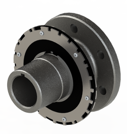
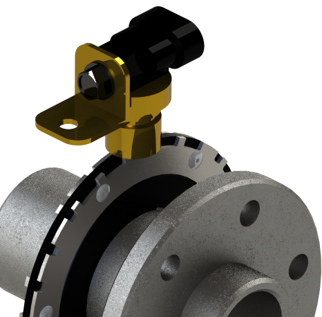
Stock/Factory LS 24x Dual Track Reluctor
|
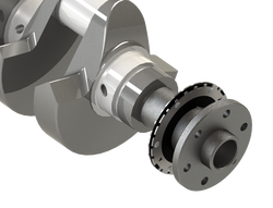
To produce the 24x crank signal, it is imperative that the signal come directly from the crankshaft. This means the 24x reluctor disc must be mounted on and rotate with the crankshaft,
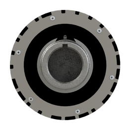
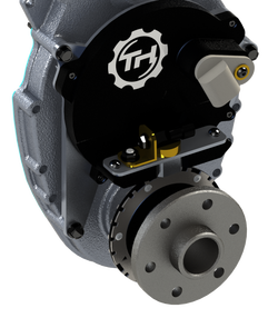
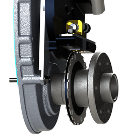
The 24xLink kit utilizes an externally mounted dual track 24x reluctor disc. The disc is precisely positioned during production on a billet keyed crankshaft hub. This results in an incredibly easy installation and the key way in the crank hub ensures accurate orientation between the 24x reluctor and piston position. No mistakes can be made here. Simply replace the existing hub with this hub assembly and your done installing the 24x reluctor that the crank sensor will read. TorqHead has chosen to utilize a true-to-form 24x reluctor that has a "dual track" like GM intended for 24x. Dual track means that there are actually two seperate discs read by the crank sensor that are 180 deg. opposed. This dual track, in conjunction with the proper dual track crank sensor, creates a high performance 24x crankshaft waveform necessary for the 24x Gen III PCM conversion. GM utilized dual track reluctors to provide better accuracy and faster starts vs a single track reluctor/single track sensor. The dual track crank sensor is more expensive but it was designed to read 24x waveform and is superior in construction for internal circuit performance/reliability. The most important sensor needs to be the BEST!...Period! |
Sensing the 24x Crank Reluctor - Familiar looking but this time 24x!!
|
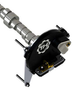
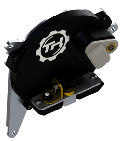
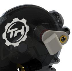
24xLink Sensing Unit
|
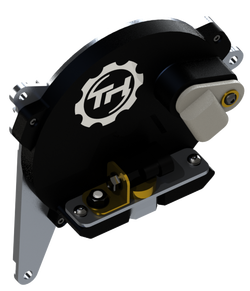
The 24xLink kit uses an externally mounted dual track crank sensor which is conveniently located on a patent pending all-in-one crank/cam signal sensing unit. This all-in-one sensing unit utilizes a opti-spark base to mount to the timing cover and connect to the camshaft. By using GM designed optispark base this solution produces optimal and accurate crank sensor positioning without the need for separate mounting arms or components. It is also no more difficult to install or setup then replacing an original optispark.
Why is the positioning so accurate? Here's why.... The distance between the crank bore and cam bore on an engine is very tightly controlled to within a thousandths of an inch. Since the opti-spark base is positioned relative to the cam bore and the 24x reluctor wheel is positioned relative to the crank bore a very accurate and secure relationship (sensing gap and position) is established between the two. To ensure the crank sensor is perfectly aligned over-top of the crank reluctor disc we have designed an adjustable crank sensor mount. Simply drop in the supplied alignment tool and tighten the crank sensor mounting screws. Just like that, the sensor is perfectly positioned over the reluctor disc to ensure an accurate and clean signal. This allows you to adjust to different timing sets and components. You should never have to adjust the mount after initial install, even if you R&R the complete assembly. Set it once and forget it!! |
Making the 1x Cam Signal
|
To produce the 1x camshaft signal, it is imperative that the signal come directly from the cam. This means the 1x reluctor disc must be mounted on and rotate with the camshaft,
Inside the 24xLink kit sensing unit, similar to a optispark, is the 1x camshaft reluctor. The 1x disc is precisely indexed and secured inside the sensing unit relative to the camshaft. The reluctor is also large enough in diameter that it produces great angular resolution to further increase the accuracy and repeatability of this design. |
Sensing the 1x Cam Reluctor
Wiring Changes - Connecting Your LTx to its new brain
|
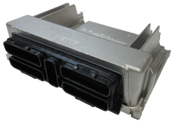
12200411 PCM - OEM LS-Style Connector Ports
12200411 PCM - TH Re-Engineered with LT1 Connector Ports LT Engine Harness PCM Connectors can now directly connect to LS Gen 3 PCM |
The Gen III LS PCM needs to be connected to the various engine components on the LT engines. These include fuel injectors, coolant sensor, 24x crank sensor, 1x crank sensor, etc, the list goes on. The problem is the factory LT engine harness, unlike the original LT PCM, does not connect to the new Gen 3 pcm. The connectors are vastly different. So this is a hurdle that must be overcome.
The goal of TH was to have no modification made to the stock OEM engine harness. No repining connectors or buying an entirely new or modified harness. LT engines harness' are OEM quality, in excellent working order and already installed properly connected to the engine sensors/actuators. It would be great if it stays where it is. The commonality of sensors and wiring strategy between LT1 and LS1 is actually surprisingly similar when comparing schematics. Hence why the LT1 PCM connectors can be re-pinned to LS1 PCM connectors. Due to this commonality there must be a more elegant Plug and Play way to accomplish this. Now, unavoidable is the addition of a small wiring harness that connects the Gen III PCM to the new ignition coils, cam sensor, and crank sensor as obviously the LT1 original harness didn’t have these components. However this is a small harness and easily added to the engine bay with ease and no permanent modification to any other part. In order to reach the goal of no harness modification, TH took something GM designed that is definitely required (Gen III PCM!!) and re-worked it for the LT engine application. TH presents the 24xLink Gen III PCM made for LT1 Engines. 'Gen III PCM on the inside, LT1 connections on the outside'. Simply plug in your stock LT1 engine harness connectors and all the proper wiring connections between the LT1 sensors and actuators are made inside the box for this conversion. Proprietary and robust electronics were employed on the inside of the OEM 12200411 PCM to accomplish the necessary connection pathways. None of the sensitive electronics GM designed for reliability are compromised. |
So whats left to make it all work, and will the engine fire?
Once the engine is connected to the PCM and the 24x/1x signal generating components are installed it is fair enough to say the toughest parts to the conversion are done. The PCM is connected and receiving all the signals it requires. The PCM is ready to be in control of the engines fuel, ignition and other compatible engine hardware. All that remains is to install the 8 necessary ignition coils, upload a proper tune, double check everything, and fire the engine!!. Unknown to the Gen 3 PCM is the fact that it is now controlling a LTx engine. Your LTx engine now is able to enjoy all the benefits and features of having a Gen 3 PCM and coil-per-plug distributor-less ignition system.

